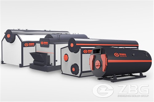
Horizontal Fire Tube Steam Boiler Type and Structure
BOILER TYPE
(a)Steam boiler shall be packaged type horizontal fire tube boilers. Each boiler shall be capable of operating on the following fuels:-
i.Town Gas -17.27 MJ/m3 calorific value
-2 to 7.5 kPa pressure
(b)Each boiler shall be of full three pass design, one pass being to combustion chamber radiant zone and two passes of fire tube.
(c)Each boiler shall be of ‘wet-back ‘ design. Back plate shall be provided with inspection/soot clean out doors. Clean out doors shall be of minimum dimension 450mm suitable for man access and installed at appropriate locations to facilitate soot cleaning.
(d)The boiler shall have-tube withdrawal from the front. The Contractor shall be responsible for ensuring that there is sufficient space for tube withdrawal in the boiler plant room. Tube access from the front shall be via hingd access doors, bolted to the boiler shell in its operating position.
(e)Burner shall be mounted on to the boiler so as to allow easy access to combustion chamber. Burner shall be bolted on to the boiler in its operating position.
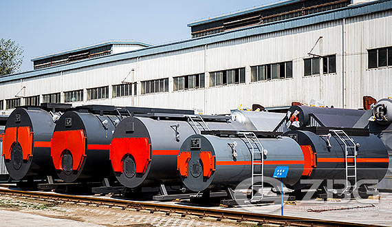
Horizontal Fire Tube Steam Boiler
STEAM BOILER CONSTRUCTION
(a)All parts of the boiler subjected to the working pressure shall be manufactured form boiler quality mild steel plate to BS 1501, and shall be welded construction to BS 2790.
(b)Plain tubes are expanded and stay tubes are expanded and welded into the tubeplates All tube ends in the combustion chamber are finished flush and welded.
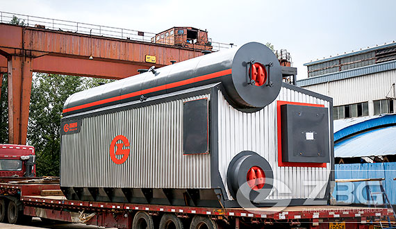
(c)The boiler shell shall be externally insulated with min. 75mm thickness of high density mineral wool, firmly banded in position and finally encased in high grade 20swg thick 'zintec' treated cladding, which is coated externally in a hot dip "Stelvetite" finish and provides a smooth finishing. The insulation shall comply with B.S. 5422. The touch temperature of the external surface of the boiler shall not exceed 45°C based on room temperature of 40°C.
(d)All exposed metal parts of the boiler shall be degreased, painted with two coats of primer, and finished with a high gloss spray paint, suitable for temperatures at boiler max. loading, and to a colour approved by Arch.
(e)Each boiler shall contain in one unit all necessary ancillary equipment such as burner draft fan, burner, feed pump. The whole unit shall be mounted on a sturdy mild steel base frame, with built-in jacking points, and lifting plugs. The base frame shall include mounting space for burner draught fan and feed pump.
(f)Each boiler shall have permanently installed access ladders and platforms, all with handrails affixed to allow access to safety valves and main steam stop valves. The platform shall not obstruct easy access to the boiler and shall include an access manway located on the boiler crown. Other plant or equipment at high level requiring adjustment during operation, periodic testing/maintenance/seivice shall be provided with suitable access ladders, and platform, all with handrails affixed.
(g)Each boiler shall be complete with all necessary steam and water mountings including:-
i.One twin spring seated safety valve with easing levers or two single spring valves. (Discharge pipes to terminate with blow off attenuates of approved design external to building).
One angle pattern main steam stop valve complete with locking device
iii.One anti-syphoning valve
iv.One steam pressure gauge, graduated with working pressure and safety valve lift indication
v.Two water gauges
vi.Water controllers shall be fitted to the boiler and shall be on separate standpipes.
a.Internal electrical probe type level controls for checking of the water level at 1" low water and 2"" low water alarm condition.
b.High water alarm and pump ON/OFF control signal is also provided via the internal electrical probes.
c.1st low water will provide a signal to the boiler/burner controls and cut out the burner which will then give a signal.
d.2nd low water will provide a signal to the boiler/burner controls and lock out the burner and give an alarm. This 2nd low water level lock out requires mandatory manual reset.
vii.Main b|ow-down valve and key, for manual blowdown and separate branch for automatic blowdown.
VIII. M I i
ix.A nameplate giving:- Maker's Name, Series and Type, Serial Number, Rated Output, Design Pressure, Hydraulic Test Pressure, Maximum Working Pressure, Date of Manufacture.
x.A plate, bearing a distinct and easily visible individual boiler number as agreed with the engineer/arch where two or more boilers are provided.
xi.Inspection port to combustion chamber. Water controllers shall be fitted to the boiler and shall be on separate standpipes.
xii.Water test cock.
xiii.Water sampling cock
xiv.Self~~cleaning flame view port with high temperature resistant glasses for combustion chamber.
xv.Thermometer, 100:-nm dia., with red pointer set to indicate flue gas temperature Water sampling cock
xvi.Multistage feed water pump complete with interconnection pipework
Automatic TDS control.
- >>Previous: Specification Sheet of 350 BHP High Pressure Steam Generating Boiler
- >>Next: Supplying, Installing And Operating Steam Boiler 38kg/cm² Refinery Co.
Hot Product
-
WNS Fire Tube Boiler
-
SZS Series Oil And Gas Fired Boiler
-
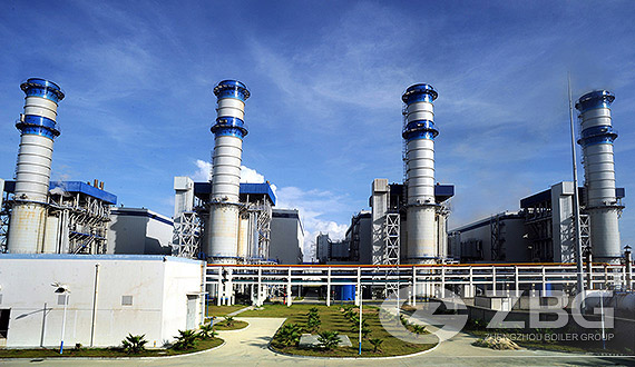
Gas / Oil Fired Power Plant Boiler